- info@jmcad.in
- B-1001, 10th floor, Sun West Bank, near shiv cinema ashram road Ahmedabad, Gujarat 380015
CNC & VMC Manufacturing Production Engineering
CNC & VMC Manufacturing Production Engineering
01_ 2 Axis CNC lathe Training Programming
02_ 2.5 Axis Turan Mill & VTL Programming
03_ 3 Axis Milling & VMC Programming
04_ 4 Axis Mill Rotary Programming
05_ 5 Axis Mill Multi Axis Programming
06_ Wire Cut Programming
07_ EDM Maching Programming
08_ VMC - CNC Operating Cum- Programming
09_ CMM Programming
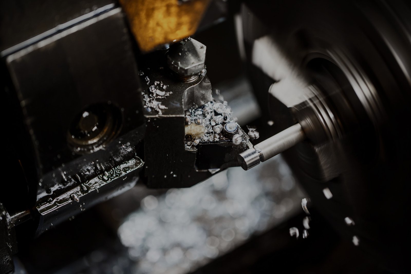
01_ 2 Axis CNC lathe Training Programming
In CNC machine tool, each axis of motion is equipped with a driving device to replace the hand wheel of the conventional machine tool. A axis of motion is defined as an axis where relative motion between cutting tool and work piece occurs.
CNC programming (Computer Numerical Control Programming) is utilized by manufacturers to create program instructions for computers to control a machine tool.
CNC is highly involved in the manufacturing process and improves automation as well as flexibility
OUR Course
02_ 2.5 Axis Turan Mill & VTL Programming
A 2.5 Axis machine, also called a two-and-a-half-axis mill, possesses the capability to translate in all three axes but can perform the cutting operation only in two of the three axes at a time due to hardware or software limitations, or a machine that has a solenoid instead of a true, linear Z axis.
The term "vertical turret lathe" (VTL) is applied to machines wherein the same essential design of the horizontal version is upended, which allows the headstock to sit on the floor and the faceplate to become a horizontal rotating table, analogous to a huge potter's wheel.
OUR Course
03_ 3 Axis Milling & VMC Programming
3 Axis Milling. 3 Axis Milling – Milling is the machining process of using rotary cutters to remove material from a piece of metal, wood, foam, or plastic, to form the piece into a specific shape. 3 Axis Milling is employed when the cutting requires simultaneous controlled movement of the X, Y and Z axes.
An axis is a direction of motion controlled by the CNC machine control. ... A 2.5axis machine really has three moving axes, but only two axes can move together (most machines sold today are full three axis machines). For machining centers, a three axis machine will have three linear axes.
OUR Course
04_ 4 Axis Mill Rotary Programming
A 4-axis CNC machine operates on the X,Y and Z axes like a 3-axis machine, but it also includes rotation around the X-axis, which is called the A-axis. This is the 4th axis that's added to our machining process. In most cases, the work piece will be rotated to allow for cutting to occur around the B-axis
A 4-axis CNC machine operates on the X,Y and Z axes like a 3-axis machine, but it also includes rotation around the X-axis, which is called the A-axis. This is the 4thaxis that's added to our machining process.
OUR Course
05_ 5 Axis Mill Multi Axis Programming
The term “5-axis” refers to the number of directions in which the cutting tool can move. On a 5-axis machining center, the cutting tool moves across the X, Y and Z linear axes as well as rotates on the A and B axes to approach the work piece from any direction.
5-axis machining refers to a machines ability to move a tool or a part in five different axes simultaneously. Basic machining operates on three primary axes, X,Y and Z; however, a 5-axis CNC machining tool can rotate two additional axes, A and B, which give the cutting tool a multidirectional approach.
OUR Course
06_ Wire Cut Programming
CNC Wire Cut Introduction. Wire EDM cutting, also known as electrical discharge machining, is a process that uses an electrically energized thin wire to slice through metal. Wire EDM cutting uses rapid, controlled, repetitive spark discharges from the wire to the work piece, thereby eroding the metal away.
In wire electrical discharge machining (WEDM), also known as wire-cut EDM and wire cutting, a thin single-strand metal wire, usually brass, is fed through the work piece, submerged in a tank of dielectric fluid, typically deionized water.
OUR Course
07_ EDM Machining Programming
CNC EDM cutting, also known as electrical discharge machining, is a process that uses an electrically energized thin wire to slice through metal. EDM cutting uses rapid, controlled, repetitive spark discharges from the wire to the work piece, thereby eroding the metal away.
In Electric Discharge Machining process an arc is produced when two current-carrying wires are short-circuited. ... this phenomenon is used in electric discharge machining (EDM). EDM machining process is also known as spark erosion machining
OUR Course
08_ VMC - CNC Operating Cum- Programming
CNC is a type of motion control system. It basically means that instead of using cams or templates to cut a part, it is controlled by a computer. A VMC is a type of CNC machine, typically enclosed and most often used for cutting metal. They are usually very precise and very expensive.
A horizontal machining center (HMC) is a machining center with its spindle in a horizontal orientation. This machining center design favors uninterrupted production work. One reason for this is that the horizontal orientation encourages chips to fall away, so they don't have to be cleared from the table.
OUR Course
09_ CMM Programming
A coordinate measuring machine (CMM) measures the surface area of three-dimensional objects. These machines are often used during the inspection phase in the manufacturing process. CMM programmers interpret object blueprints and program the CMM to take accurate measurements.
These machines can be manually controlled by an operator or they may be computer controlled. Measurements are defined by a probe attached to the third moving axis of this machine.
